
My Janky wall-mounted eGPU Build Log
you can just do things the wrong way

A pieced-together build log of a little project I did in 2020
Back 5 years ago during the pandemic, I had my trusty old XPS 13 laptop, faced an issue: I had just gotten a second external monitor, but I could only drive one external display off my laptop. What ever could I do?
I also had a desktop PC, but my mom was using it, and I kinda liked the convenience of being able to bring my laptop around to university and to have all my things set up on one device. I had been an enjoyer of LinusTechTips and AnandTech and such.
I had some spare parts from an old PC with an old GPU and a Power Supply laying around, and was considering buying an eGPU enclosure, but there were quite costly, and I didn’t want to spend all my money on this.
Whatever could I do?
I spent some time searching, and wondered whether one might be able to get a simpler solution off AliExpress or similar. There was some discussion, and it did seem possible at least. So I set out on my little journey.
The first was to choose a class: Which of two eGPU methods did I want?
The first involves opening up your laptop, using any spare PCIe lanes you might be able to find (either from a spare NVMe slot or from a networking slot) and connecting to the board. Pretty cheap and easy to find.
The second involves using a USB-C thunderbolt connection
The latter was preferable for me, since my laptop did already have Thunderbolt 2 (not as good as Thunderbolt 3 for these purposes, but it would make do) and I really didn’t like the need to unscrew the bottom of my laptop.
However, finding boards for the latter is slightly more difficult. Most eGPU enclosures on the market used USB-C boards, but I didn’t need the whole box and PSU and such that came with it, and those things added a lot of cost to the enclosure.
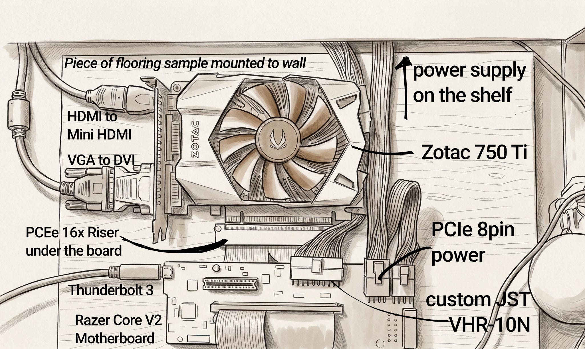
But there did sometimes exist a very small market of boards-only on sites like AliExpress. I found a perfect contender, the Razer Core V2 enclosure, but they were no longer selling on AliExpress.
After searching, I found that there WAS someone in Poland who had presumably done the same as me, and who now done with it and selling the board online for 399 Zloty.
Perfect.
I hit up the DMs of the random polish dude on Allegro, and asked if he could ship it to me in Ireland. He said yes. So I sent the money, and started ordering other things I might need.
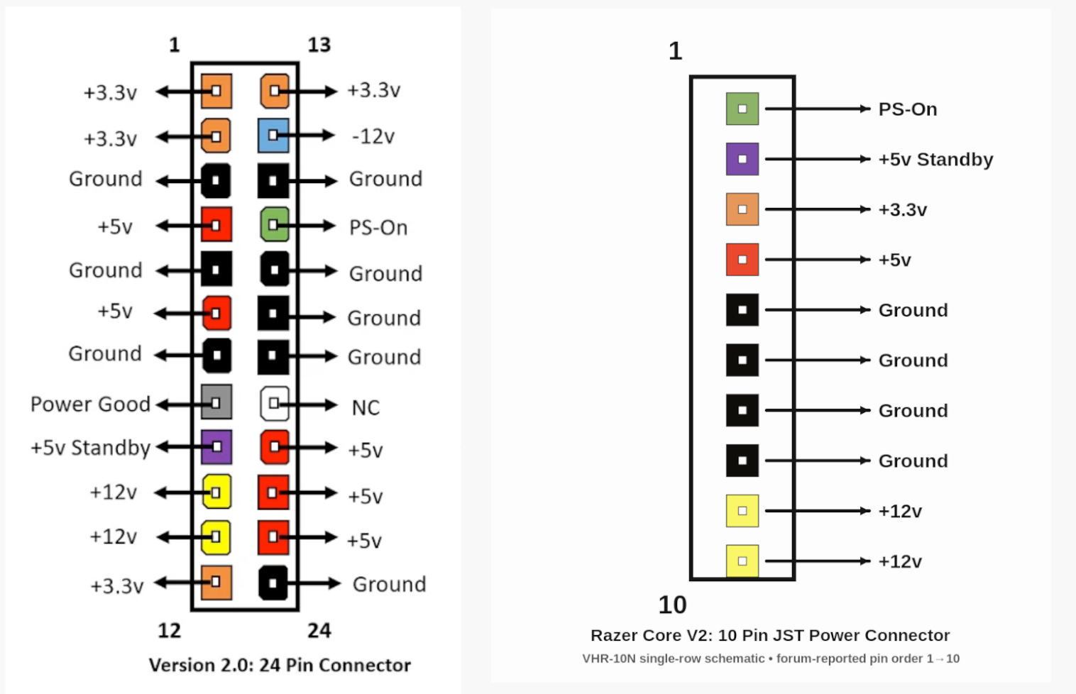
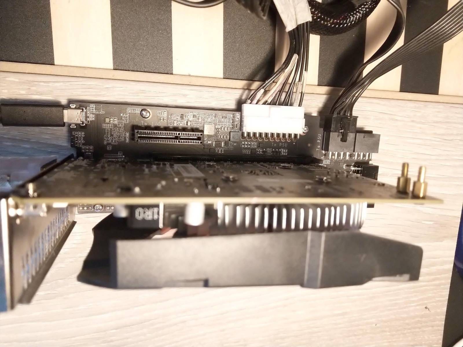
The first thing I needed to deal with was the power connector. Most PCs use a standardized 24-Pin ATX cable. The the Razer Core V2 chose to be quirky and to have a weird 10-pin connector (JST VHR-10N).
This means that it would be non-trivial to get the board powered. Luckily, someone online had described the pin-out online. So I just needed to make a custom power connector to translate between the two connectors:
Since I was student on a budget, I thought not “how do I make sure this is not a fire hazard” and instead thought “how can I just barely get this working for little money”.
The correct way to do this is:
buy an ATX connector
buy a 10-pin connector
buy some quality, 18AWG wire
cut wires to equal lengths, strip, and connect together using a crimping too.
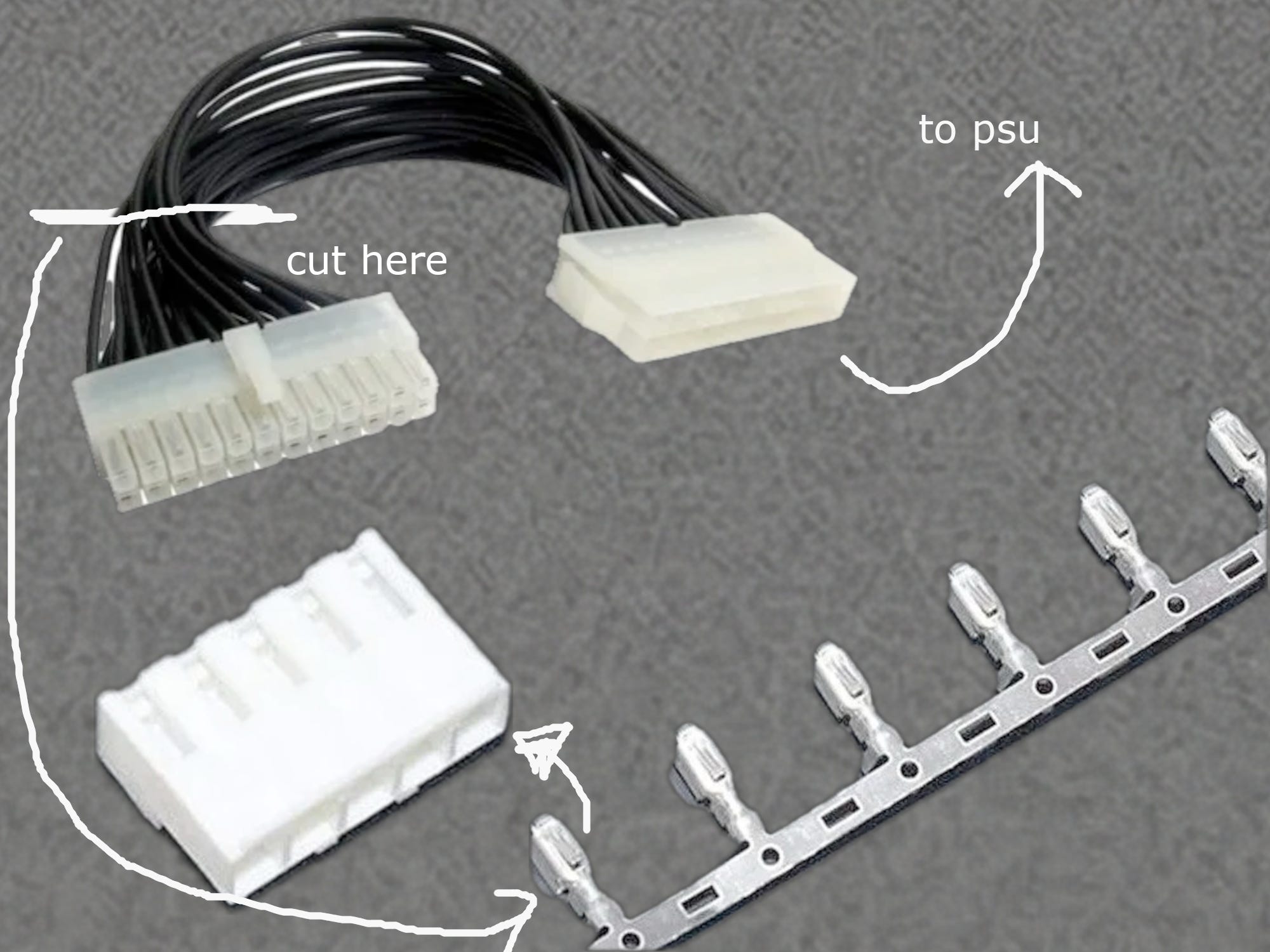
That sounds like effort, who the heck needs a crimping tool? I don’t want to buy a crimping tool. Instead, the cheapest way to get this to work, was:
a very cheap 24-pin ATX to 24-pin ATX extension cable
a JST VHR-10N connector
some JST VHR crips
cut the head of the 24-pin cable off and remove unused wires
strip the wires and use a set of pliers to crimp them and connect them into the JST connector
Here is a explanation diagram of my plan:
I needed to follow a slightly annoying pin out diagram. I checked and checked and checked that it’s correct. I labelled the wires with masking tape and coloring it in.
I may have completely destroyed a couple of crimps with my pliers, but it was fine because I had a few spares. Then I got it to work! It connected!
I plugged in my bodged power cable, and the normal PCIe 8-pin connectors, plugged in the GPU, and the cable, and the power supply powered on.
I first tested it in windows, but then I came up to some secondary issues. At the time, I was mainly using Arch Linux (btw)1 and so getting anything to work sucked. (but I loved the pain)
After searching on some forums, someone smarter than me had already solved this issue! I basically just went on the form, blindly copy pasted two different scripts to my laptop, and moment of success, it worked!
Now I just needed to tidy it all up.
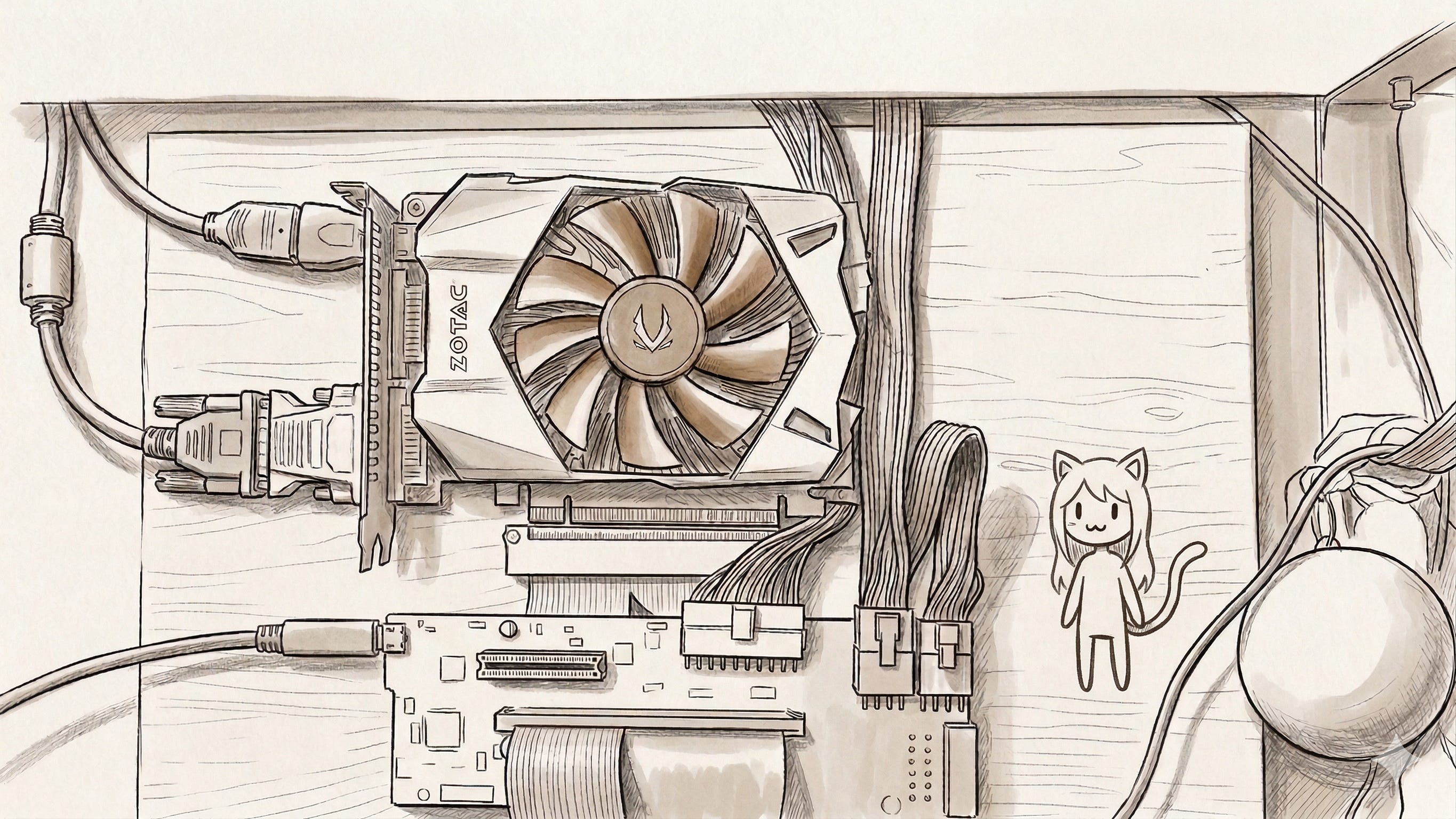
I took my piece of flooring sample that I got, drilled some holes into it where the standoffs need to go, screwed in the standoffs.
I then also connected my 16x PCIe Power connector to flow under the the board, and mounted the GPU to the piece of flooring sample.
I then drilled a hole in my parent’s wall below where I installed a shelf, lay my PSU directly above the shelf (where I had my monitors already mounted), and screwed the piece of flooring into the wall. I could connect my two monitors now.

Thus I had this beautiful setup which was clean and minimalist, and didn’t take up much space on my low-depth desk, and never had any clutter at all. (shown above)
How was the experience using it?
It was OK I guess…
I found it pretty annoying that I couldn’t hot connect and disconnect my laptop and had to have extra steps before plugging it in and out. (I think I had to restart it, but maybe I just had to run some scripts or something, I don’t remember)
Was it good for gaming at least? Ehh, maybe slightly better. I planned to maybe connect a better GPU some time but I never got around to it, and ended up just getting a dedicated desktop PC some time anyway.
Oh and I guess it did work with 2 monitors at least, so that was nice.
Ok ngl I was actually a LARPer and was using Manjaro Linux (which is arch-based) because I liked the defaults tbh